The alternator excitation circuit includes the necessary components and devices to generate the alternator output voltage.
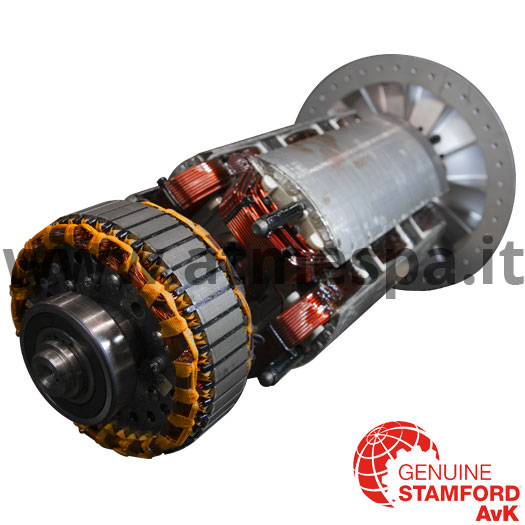
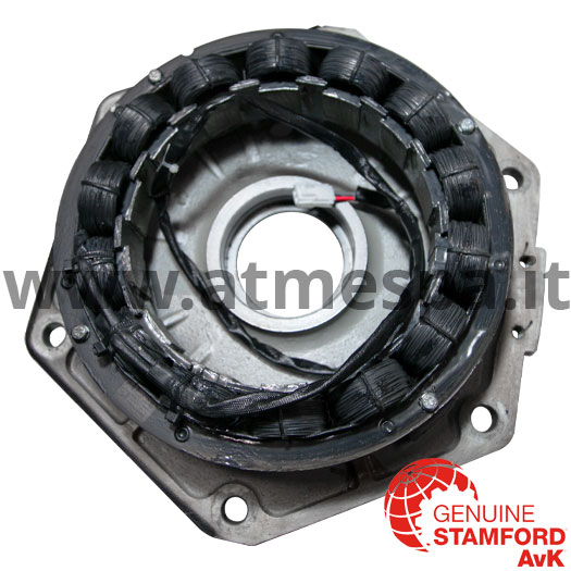
It mainly comprises the exciter stator, normally fixed inside the shield on the free side (NDE) of the machine, and the exciter rotor, keyed on the alternator shaft and which rotates inside the stator.
The materials used for their manufacture are mainly copper conductors wound to form coils (windings) suitably housed in shaped ferromagnetic steel lamination quarries.
The excitation stator is powered by a DC voltage from the AVR voltage regulator. The direct voltage generates a magnetic field which strikes the turns of the windings of the exciter rotor.
The excitation rotor is one of the two components of an AC generator and is part of the excitation circuit of the alternators, coupled with the excitation stator.
The exciter rotor produces by induction a three-phase AC voltage as it rotates on the main rotor shaft, within the exciter stator.
The three-phase alternating voltage is subsequently transformed into direct voltage by the diodes connected to the excitation rotor windings.
The excitation stator and rotor, and the rectifier diodes, are therefore the source of energy to obtain a potential difference necessary to circulate a current in the windings of the main rotor and thus generate a magnetic field.
The voltage induced in the exciter rotor varies according to the voltage supplied to the exciter stator by the AVR, which monitors the voltage at the alternator output terminals.
When the alternator output voltage drops below the preset level, the AVR increases the exciter stator supply voltage; the diodes receive a higher voltage from the exciter rotor and therefore the intensity of the magnetic field increases. It also increases the output voltage proportionally.
If the voltage at the output terminals rises above the preset level, the AVR will reduce the voltage at the exciter stator, having the opposite effect.
The good functioning of the alternator depends, among other factors, on the good electrical insulation of the windings.
The electrical, mechanical and thermal stresses and the chemical and environmental contamination cause the decay of the insulation and the increase of the probability of failure, even destructive, of the windings.
To ensure the consistent operation and long-term lifespan of your alternator it is essential you buy genuine.
Buying a genuine STAMFORD® | AvK® spare-part ensures:
- Don’t lose the validity of the alternator warranty;
- Minimised risk of plant and equipment failure;
- Maximised power supply security;
- Matched performance capability to alternator ensuring stability and responsiveness;
- A product that is tested to react in emergencies, triggering support existing protection systems.
Spare parts have a 12 month warranty.
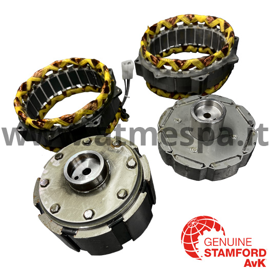
Permanent Magnet Generator (PMG)
The permanent magnet generator is an auxiliary component used to supply independent power to the AVR. It is made up of a wound armature stator and a rotating field rotor. As its name implies, the magnetic field is supplied by a number of permanent magnets contained in an iron core. These magnets do not rely on DC current to generate a magnetic field. The rotor is fixed to the main rotor shaft of the generator and rotates at the same speed as the main rotor.
Advantages
One advantage is its ability to continue providing power to the AVR if there is a large load applied to the generator. On a self-excited machine (without PMG) if a large drops the main generator output voltage too low, the AVR could shutdown. This would shut off excitation and cause the generator output to fall to zero. A separate power supply (with PMG) prevents this from happening. Another advantage is that it does not rely on residual magnetism which can be unreliable at times. The additional costs are justified by the benefits brought.
To ensure the consistent operation and long-term lifespan of your alternator it is essential you buy genuine.
Buying a genuine STAMFORD® | AvK® spare-part ensures:
- Don’t lose the validity of the alternator warranty;
- Minimised risk of plant and equipment failure;
- Maximised power supply security;
- Matched performance capability to alternator ensuring stability and responsiveness;
- A product that is tested to react in emergencies, triggering support existing protection systems.
Spare parts have a 12 month warranty.
Anti-condensation heaters
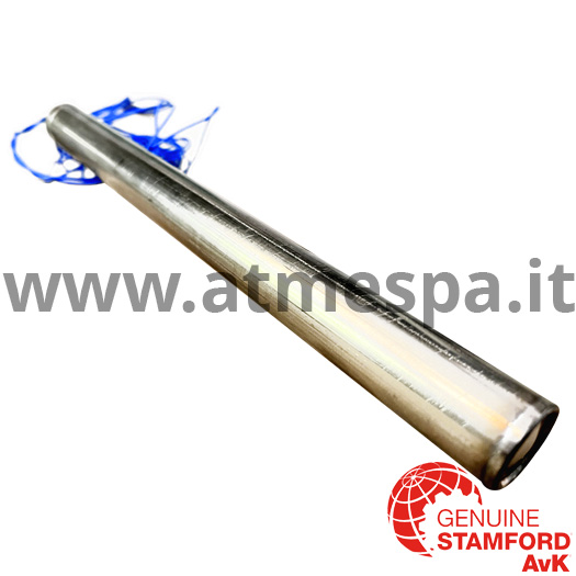
The purposes of using anti-condensation heaters is to raise the temperature inside a stationary generator above the dew poin temperature. This is important to prevent destructive damage to the alternator windings, especially in generators that go long periods of time without use. They also prevent condensation buildup after shutdown of a generator in high humidity environments. The heater can take the form of a cartridge element mounted on the generator frame or a ribbon heater that surrounds the stator windings on the outside.
To ensure the consistent operation and long-term lifespan of your alternator it is essential you buy genuine.
Buying a genuine STAMFORD® | AvK® spare-part ensures:
- Don’t lose the validity of the alternator warranty;
- Minimised risk of plant and equipment failure;
- Maximised power supply security;
- Matched performance capability to alternator ensuring stability and responsiveness;
- A product that is tested to react in emergencies, triggering support existing protection systems.
Spare parts have a 12 month warranty.


